Friday 6 December 2013

 Bluetooth Connection in Android from Matt Bell's blog

Project Structure


Here is the java and xml code from Matt Bell's blog adapted to send data only:

[code]--------------------------------------------------------------------------------------

package here
imports here

public class BluetoothTest extends Activity
{
    TextView myLabel;
    EditText myTextbox;
    BluetoothAdapter mBluetoothAdapter;
    BluetoothSocket mmSocket;
    BluetoothDevice mmDevice;
   
    OutputStream mmOutputStream;
   

    @Override
    public void onCreate(Bundle savedInstanceState)
    {
        super.onCreate(savedInstanceState);
      
        setContentView(R.layout.activity_main); // need a activity_main layout XML file
// with these objects below in it (buttons, labels etc...):
      
        Button openButton = (Button) findViewById(R.id.open);
        Button sendButton = (Button) findViewById(R.id.send);
        Button closeButton = (Button) findViewById(R.id.close);
        myLabel = (TextView) findViewById(R.id.label);
        myTextbox = (EditText) findViewById(R.id.entry);

        // Open BT connection Button
        openButton.setOnClickListener(new View.OnClickListener()
        {
            public void onClick(View v)
            {
                try
                {
                    findBT();
                    openBT();
                } catch (IOException ex)
                {
                }
            }
        });

        // Send Button
        sendButton.setOnClickListener(new View.OnClickListener()
        {
            public void onClick(View v)
            {
                try
                {
                    sendData();
                } catch (IOException ex)
                {
                }
            }
        });

        // Close button
        closeButton.setOnClickListener(new View.OnClickListener()
        {
            public void onClick(View v)
            {
                try
                {
                    closeBT();
                } catch (IOException ex)
                {
                }
            }
        });
    }

    void findBT()
    {
        mBluetoothAdapter = BluetoothAdapter.getDefaultAdapter();
        if (mBluetoothAdapter == null)
        {
            myLabel.setText("No bluetooth adapter available");
        }

        if (!mBluetoothAdapter.isEnabled())
        {
            Intent enableBluetooth = new Intent(BluetoothAdapter.ACTION_REQUEST_ENABLE);
            startActivityForResult(enableBluetooth, 0);
        }

        Set<BluetoothDevice> pairedDevices = mBluetoothAdapter.getBondedDevices();
        if (pairedDevices.size() > 0)
        {
            for (BluetoothDevice device : pairedDevices)
            {
                if (device.getName().equals("linvor"))// change accordingly
                {
                    mmDevice = device;
                    break;
                }
            }
        }
        myLabel.setText("Bluetooth Device Found");
    }

    void openBT() throws IOException
    {
        UUID uuid = UUID.fromString("00001101-0000-1000-8000-00805f9b34fb");                                                                                                                                                         

if (mmDevice != null) 
        {
            mmSocket = mmDevice.createRfcommSocketToServiceRecord(uuid);
            mmSocket.connect();
            mmOutputStream = mmSocket.getOutputStream();           

       
        myLabel.setText("Bluetooth Opened");
        }
    }


    void sendData() throws IOException
    {
        String msg = myTextbox.getText().toString();
        msg += "\n";
        mmOutputStream.write(msg.getBytes());
        myLabel.setText("Data Sent");
    }

    void closeBT() throws IOException
    {
      
        mmOutputStream.close();
        mmSocket.close();
        myLabel.setText("Bluetooth Closed");
    }
}// end of java code.


XML code: 
Manifest

<?xml version="1.0" encoding="utf-8"?>
<manifest xmlns:android="http://schemas.android.com/apk/res/android"
      package="your package"
      android:versionCode="1"
      android:versionName="1.0">
    <application android:label="@string/app_name" >
        <activity android:name="BluetoothTest"
                  android:label="@string/app_name">
            <intent-filter>
                <action android:name="android.intent.action.MAIN" />
                <category android:name="android.intent.category.LAUNCHER" />
            </intent-filter>
        </activity>
    </application>
    <uses-sdk android:minSdkVersion="5" android:targetSdkVersion="9"/>
    <uses-permission android:name="android.permission.BLUETOOTH" />
    <supports-screens android:anyDensity="true" />
</manifest>


Layout:

<?xml version="1.0" encoding="utf-8"?>
<RelativeLayout xmlns:android="http://schemas.android.com/apk/res/android"
    android:layout_width="fill_parent"
    android:layout_height="fill_parent">
    <TextView
        android:id="@+id/label"
        android:layout_width="fill_parent"
        android:layout_height="wrap_content"
        android:text="Type here:"/>
    <EditText
        android:id="@+id/entry"
        android:layout_width="fill_parent"
        android:layout_height="wrap_content"
        android:background="@android:drawable/editbox_background"
        android:layout_below="@id/label"/>
    <Button
        android:id="@+id/open"
        android:layout_width="wrap_content"
        android:layout_height="wrap_content"
        android:layout_below="@id/entry"
        android:layout_alignParentRight="true"
        android:layout_marginLeft="10dip"
        android:text="Open" />
    <Button
        android:id="@+id/send"
        android:layout_width="wrap_content"
        android:layout_height="wrap_content"
        android:layout_toLeftOf="@id/open"
        android:layout_alignTop="@id/open"
        android:text="Send" />
    <Button
        android:id="@+id/close"
        android:layout_width="wrap_content"
        android:layout_height="wrap_content"
        android:layout_toLeftOf="@id/send"
        android:layout_alignTop="@id/send"
        android:text="Close" />
</RelativeLayout>


Arduino Test Code:
#include <SoftwareSerial.h>

int bluetoothTx = 2;
int bluetoothRx = 3;

SoftwareSerial bluetooth(bluetoothTx, bluetoothRx);
const int LED = 10;
char incomingByte = ' ';

void setup()
{
  //Setup usb serial connection to computer
  Serial.begin(9600);
  pinMode(LED, OUTPUT);
  //Setup Bluetooth serial connection to android
  bluetooth.begin(115200);
  bluetooth.print("$$$");
  delay(100);
  bluetooth.println("U,9600,N");
  bluetooth.begin(9600);
  Serial.println("Start");
 
}

void loop()
{


  //Read from bluetooth and write to usb serial
  if(bluetooth.available())
  {
    Serial.println("BlueTooth OK");
    char toSend = (char)bluetooth.read();
    Serial.println(toSend);
    incomingByte = toSend;
  }


if (incomingByte == 'l')
{
digitalWrite(LED, HIGH);
delay(500);
digitalWrite(LED, LOW);
}
 
}


[end code]----------------------------------------------

Friday 11 October 2013

FrankenTech Case Hack

Motorola micro TAC from 1995

Introduction

I have a 1995 Motorola micro TAC mobile phone. I'm am going to FrankenTech it by putting in a modern GSM party phone. I will have to lose the retro keypad to keep the functionality of the party phone. I think I will need to keep the speaker too -not sure at this stage. So don't rush in and cut the speaker out!

It is just a case hack, but I always liked the look and feel of that old phone. Somewhat Treky (flip cover) and military looking (antenna). The party phone VX1 was £10 from Tesco, Text and voice only.

Ideally I would love to use the Motorola as is, but there is no way to use it with a SIM. It will also  be chargeable via USB. Resistance is futile - you will be assimilated!

Here are the parts:

It should turn out something like this artist's impression:
FrankenPhone

Method

As with all cutting of cases and plastic boxes, to make a neat job, it's about patience and having good tools. I used these:
  • a very sharp sturdy craft knife (these are often called Stanley knives in the UK).
  • a jewellery-type piercing saw
  • a cutting board
  • a set of needle files
  • craft drill and toolset
  • small jeweller's round nose pliers
  • side cutters
Opening the case
 There are no screws on this case. It is all moulded plastic with lugs that hold it together. That makes it tricky to open without damage. I used the small round nose pliers to push aside the lugs.

 Case already open showing lugs and slots.

  • first remove the battery on the back
  •  locate the four slots with lugs
  • as gently as you can use a tool (I used small round nose pliers) to push the lugs towards the outside of the case. This should pop them out of place and allow partial opening, with each lug popped in turn.
  • remove the back
  • carefully remove all of the innards of the phone, but leave the speaker inside with the wires attached (cut wires close to circuit board)

Wednesday 21 August 2013

Whistle and Wag!

 Detect sound generated by

 Buccal Wetware

 [brain; purse lips; exhale; whistle]


A very simple and Fun Hack for Whistle and Find Device


Introduction.
This is a fun hack for those whistle and find devices. The type you attach to your remote control so you can always find it eg whistle and find device.

That ones quite expensive, but you can often find them on offer in bargain shops for a couple of quid. I bought a set years ago and had one left rattling around in one of my junk drawers. I decided to play with it because I was looking for a way to add an interactive waggy-tail to a small robot.

You also need a small servo, arduino (or similar) a photo-resistor and a 10K pull down resistor - simple!

Whistle-n-Wag Circuit

Place the led of the device right next to the sensor surface of the photo-resistor and shade it.
When you whistle the device flashes it's led and that light is picked up by the photo-resistor, this makes a circuit with the 5v supply and this voltage is detected by the analogue pin of the arduino. The video is not good quality but you can get the gist. NB you can use the whistle hardware provided with the sets, but notice I used buccal wetware to generate the sound in the video [brain->purse-lips->exhale = whistle] : )

Whistle-n-Wag Video

Arduino Code:
Servo myservo;
int wag = 0;
int pos;
//PhotoResistor Pin
int lightPin = 0;

int servopin = 7;   //the pin the servo is connected to
                
void setup()
{
  pinMode(servopin, OUTPUT); //sets the servo pin to output
  digitalWrite(servopin, LOW);  //servo OFF
  myservo.attach(7);
  myservo.write(90);
  Serial.begin(9600);
}

void loop()
{
 int lightLevel = analogRead(lightPin); //Read the
                                        // lightlevel

if (lightLevel > 450)
 {
   wag = 1;
 }

 if (wag == 1)

 {
  
   for (pos = 0; pos < 180 ; pos +=2)
   {
  

   myservo.write(pos);

  Serial.println(lightLevel);
   }
  
 }


}

Friday 9 August 2013

Positronic Brain Sim requires no MCU?

A Diamond Flashing LEDs Update II

Christmas lights, Halloween, Mood Light, Baby Light

This is a screen-shot of the positronic-brain-sim PCB design [R = red, G = green, A = amber P = pink] The LEDs are diamond cut flashing leds available here: Rapid [UK]

The design is copyright of Craig Turner 2012, 2013. But feel free to make some PCBs for personal use and enjoy them. No PCB copies should be made for sale or any commercial use.

This could be a costume Idea for Halloween (I plan to put them in a model of a human head), Christmas lights, a mood light, baby lights or any other cool lighting idea application. It's so simple, and works on the principle that each colour has differnt power requirements hence no MCU is required. It reminded me of a positronic brain you might find inside an android. See here for more details of  How it works. 

NB that LED D18 is in fact Green and not Yellow. It was mistakenly shown as yellow in an earlier post.


Here is the circuit diagram again in it's simplest form. As you can see it's just a grid of these special LEDs with a power supply (eg USB) and a switch. It runs quite happily and brightly off 5v so a USB is perfect.

I'm looking into getting some PCBs made of this simple design so I can easily share it with friends and family, the Scouts and anyone else, for that matter. Here is the art work in .jpg format if you want to etch one yourself, on my Google Drive.

See comment on Hackaday


Friday 2 August 2013

Positronic Brain Sim requires no MCU?

Costume Idea for Halloween

A Diamond Flashing LEDs Update I


D1 to D35 are diamond flashing LEDs. D36 and D37 are multicolor cycling LEDs. 

Just a quick update to the diamond flashing LEDs. I hacked a USB cable and attached this as the power source. I also added some two lead colour-cycling LEDs (not shown on video).

A bit of fun and very pretty. It might be good as a baby mobile or a calming mood light - it's quite relaxing and almost hypnotic. I decided to make it as a "pick-me-up project" for those long winter nights in 2012.  I'm now looking to use this idea to look like a positronic brain for halloween 2013 [positronic brain] inside a model of a human head.

The video speaks for itself. A very simple circuit with no MCU - the arrangement of led's makes the flashing pattern. I think it's the slightly different power requirements of the different colours that makes the pattern work.


I reasoned that blue and green need more power before they switch on, so red goes first. The red and yellow ones are last to go off as I gradually drop the power using a variable PSU.


Slowed down the video shows that red and yellow come on first before the pattern stabilizes. I'm not sure if this explanation of the pattern is correct. Please comment if you agree or not, or have any more ideas.


The design is copyright of Craig Turner 2012, 2013. But feel free to make some PCBs for personal use and enjoy them. No PCB copies should be made for sale or any commercial use.


You can get the led's here:

Saturday 22 June 2013

Earth Rover 

Part IV

Android / Arduino Interface Code Update.

Code update for android and arduino files. Note xml files are added on to end of Java code in same file to save space. You will need to cut and paste them to the correct xml files.On my google drive:


The update incorporates two way serial comms over BT. RC control from Android with bumper sensors controlling interrupts to stop the Rover and display which bumper was triggered on the display. Note I am using button action:  if (event.getAction() == MotionEvent.ACTION_MOVE)
which means you have to keep you finger or stylus moving slightly to keep sending the signal. A small safety feature.

It is an update but it isn't working fully. The interrupts are triggered incorrectly by the movement of the robot's motors. I am working towards finding out why and a solution. Please let me know if you have some ideas.

Monday 17 June 2013


Father's Day

My Dad, Jack Turner Born 1936 
 
He was the first person in our family history to get a decent education, thanks to his working class parents who struggled in impossible times to get him there.
He volunteered for the RAF as a firefighter, during the years when National Service was compulsory. He served 25 years in the W. Yorkshire Fire Service and saved many lives, nearly copping it himself a couple of times. 
It's thanks to him I became a scientist and a geek. He bought me a chemistry set when I was five and taught me about how chemicals can interact to make fire and fire-hazards. To me, at that age, means fireworks. He let me have a lab in our attic and bought me more chemistry sets, a microscope, electronics kits and other cool science stuff.
 Thanks Dad for being a great Dad, a hero, and an inspiration.
 Craig Turner [gampa geek]


Monday 20 May 2013


Earth Rover 

Part III

Providing Power, Direction and Speed Control


 Wiring the Motors, DPDT Relays and PWM to the MOSFET

Also see our new site  Eusentient.com

The diagram above shows how I wired four of the DPDT relays (on my eight relay board) to control the direction and speed of the motors for the Rover's wheels. NB the circuit for controlling the relays using an Arduino pin is ready made on the eight relay board - here.

A logic level, power N-MOSFET switches high current to provide motive power at 12vdc vdc. The gate is controlled by an Arduino PWM pin so speed can be adjusted accordingly. However each individual relay is only capable of switching 2A at 12vdc, but that can give me 24watts, per wheel in theory. There is also a 24v version.

When the Arduino PIN V1 is set to logic 1, the motor goes in one direction, and when set to logic 0 the  the DPDT relay switches it to go in the opposite direction. Fly-back diodes  (D1 and D2) are used to reduce emf spikes from the coils in the relay and motors. D1 is an integral diode in the MOSFET package.

 I decided to make a perf-board version of the Mosfet PWN driver circuit x4 using this free design app.

Mosfet PWN driver circuit x4

 I could have made it more compact, but I wanted to keep the symmetry of the design:

Perf-board Mosfet PWM driver circuit x4 with heat sinks

I glued aluminum heat sinks to the Mosfets using epoxy-based thermo-paste, and used Schottky power diodes for fly-back [those are the big black monoliths]


Saturday 18 May 2013

Earth Rover 

Part II

Android-Arduino User-Interface

Tablet Screen Shot

This is my first stab at producing a user interface to communicate with my Arduino Earth Rover over blue-tooth. I given links to the code below, it's a bit raw but there lots of work to do. You can send commands from the Android, like setting the speed and direction. Also there is some test code to confirm the sending of data from the Arduino, eg a bump sensor. When the correct data  is sent from the Rover an alert toast appears and the text of a button will change to red, depending on which side of the Rover was bumped.

***Disclaimer***
 * Please note this code is provided for free and AS IS. There is no support and no guarantee
 * from the Author. As a non-expert I am happy to answer constructive comments and questions.
 *****************
 *Subject to GNU licence version 3 and copyright of Craig Turner May 2013:

 * please use it, modify it, and enjoy it.
 * If you find it useful please link to my website:
 * http://gampageek.blogspot.co.uk/2013/05/blog-post.html
 *
 * Bluetooth coding based on Matt Bell's Blog here:
 * http://bellcode.wordpress.com/2012/01/02/android-and-arduino-bluetooth-communication/
 */
Arduino code here
Android code here


Earth Rover 

Part I

Arduino Semi-Autonomous Robot 

With Android User-Interface

Ok, I'm not even attempting to build something like a Mars roving robot  :o - but my mini budget earth rover is a good starting point for me to learn some more robotics. I've built RC and sequence (dancing) robots before see here, but not an autonomous robot with sensors that can find it's own way around a space.

I've pulled together some resources to start with, some used in previous projects:

  • A 4WD robot car chassis here

     
  • An android tablet
  • A Japanese eight module DPDT relay board from Ebay £29 [to direct power to the motors]

  • Arduino Mega 2560 dev board  from here

  • An OWI-535 Robotic Arm from here


  • An SRF05 ultrasonic sensor from here
  • A selection of micro-switches to act as bump-sensors from here


  • Discrete components such as power MOSFETs, power fly-back diodes, resistors, capacitors, leds, terminals, headers etc... from a standard electronic supplier eg here
https://upload.wikimedia.org/wikipedia/commons/thumb/e/ea/Componentes.JPG/400px-Componentes.JPG
[Image is not of actual components used]


That's a start.

Coming soon in Part II -  Arduino remote control from an Android tablet over blue-tooth.


Monday 8 April 2013


Chillout with The Relaxino Heart App

Copyright Craig Turner (Gampa Geek) April 2013. 

 A few weeks back I posted some Arduino code designed to work with the Grove Heart Rate monitor (arduino-meets-yogic-arts). Since then I have developed an Android Application that works with Arduino over Blue-tooth to display your heart rate in a tablet user interface. It also provides simple biofeedback via the screen which flashes at your heart rate. The user can choose a target rate from 30 to 100 bpm, using a sliding seek-bar. The screen changes from purple to green when the target is achieved, enabling the user to practice breathing techniques, reduce heart-rate and so achieve a better level of relaxation, through biofeedback training.

Why did I bother? Well I had a heart attack about 8 months ago so this type of thing came uppermost in my mind. I now use the prototype Relaxino hardware and app to chillout and relax the heart.


Explanation of how it works.
It works by measuring your heart rate and taking an average over 20 beats.  An LED on Arduino pin 13 flashes each time your heart beats, because each beat triggers an external interrupt.  The average heart rate is sent every 20 beats over Bluetooth to the Android device.

You set a target rate on the Android, so a purple screen flashes when you are above target and a green one when you are at, or below the target heart rate. This allows you to try to relax and get feedback on how you are doing. Lie or sit down and try to relax, taking long deep breaths in and out, empty your mind and gently focus on the screen light (being in the dark helps so you can see the pulses through semi-closed eyelids).

Geekery Recipe:
Arduino
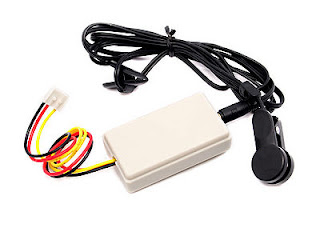
  • The device uses a RISING interrupt on pin 2, so attach the output wire (yellow) of the heart monitor to pin 2 of the Arduino.

  •  Black wire goes to ground and red to +5v.

  • Connect the Rx and Tx, power and ground of the Bluetooth module (mine is a BlueSmirf Gold) to the Arduino pins 4 and 5 respectively.
  • Attach the ear clip to your left ear. Beware some peoples ear lobes are too thick (mine are) so play around with the position. I had to put it on a thin flattish part of my ear.
  • Upload the code to the board.

  • LED on pin 13 will pulse at same rate as your heart. You can check by feeling the pulse in your neck. Both should be approx in sync.

  •  Open the serial monitor (for debug if required)

Android
  • Install the App - you can do this directly using Relaxino.apk, or create a project in Eclipse Juno, and cutting and pasting the .java and .xml files. NB the manifest and layout files are in the same .xml file. You might need the app icon too so I included it on the Google drive.
  •  Check the Arduino BT module is paired with your Android device (in Android settings). It may require a PIN but they are usually trivial numbers such as 0000 or 1234.
  •  Start the app and enter the name of your BT device eg FireFly-008A and click Open Connection.
  •  A connection should happen and a success message “Connection Opened: device_name ” appears. The message in the purple bar will say “Waiting...” If it fails just keep trying.
  •  Press reset on the Arduino – and the message should change from “Waiting” to “Sensing Heart Rate”.
  •  After 20 beats the message should read  “Your Heart Rate is: something bpm”
  • This is your actual average heart rate sent every 20 beats from the Arduino.
  • Set the target heart rate for your relaxation. When you reach the target the screen will change from flashing-purple to flashing-green.
  •  Lie or sit down and try to relax, taking long deep breaths in and out, empty your mind and gently focus on the screen light (being in the dark helps so you can see the pulses through semi-closed eyelids).
  • Gradually increase the length of the breaths, counting if you need to: 6-8 seconds for in, 6-8 seconds for out (or do whatever you can manage). Build up to longer and longer ins and outs. Don't rush it and get out of breath - your heart will beat faster!
  • With practice it can help you relax by providing simple biofeedback.
Screen Shot

Video of Relaxino

Grove Heart Rate Monitor - Ear Clip

Arduino and Android Code and App here:  Google Drive
App only is now on Google Play Relaxino
and FileDir.com 
Download Relaxino for Arduino-Android / Android
App Icon: blueglassheart.png

Check out this awesome Arduino-Android accessory dev tool.
https://play.google.com/store/apps/details?id=com.nettoraid.droidei
http://www.droidei.com/

/**
 * Communicate with Arduino over Blue-tooth to display your
 * heart rate in a tablet user interface. It also provides simple biofeedback
 * via a flashing screen which flashes with your heart rate. The user can choose
 * a target rate from 30 to 100 bpm, using a sliding seek-bar. The screen changes
 * from purple to green when the target is achieved, enabling the user to use breathing
 * techniques to reduce heart-rate and so achieve a better level of relaxation,
 * through biofeedback training.
 *
 ***Disclaimer***
 * Please note this code is provided for free and AS IS. There is no support and no guarantee
 * from the Author.As a non-expert I happy to answer constructive comments and questions.
 *****************
 *Subject to GNU licence version 3 and copyright of Craig Turner April 2013:

 * please use it, modify it, and enjoy it.
 * If you find it useful please link to my website:
 * http://gampageek.blogspot.co.uk/2013/04/chillout-with-relaxino-heart-app-few.html
 *
 * Bluetooth coding based on Matt Bell's Blog here:
 * http://bellcode.wordpress.com/2012/01/02/android-and-arduino-bluetooth-communication/
 */