Wednesday, 12 December 2012

Remote Controlled Eight-Relay Board

PART VIII

- An RC Firework Firing Device

1st Tryout With Fireworks


Four rockets fired simultaneously
Success!

I'm very pleased with how the RC device performed. It did exactly what it was designed to do, including all the safety features. I thoroughly enjoyed using the hand-held, with it's missile switch and PIN entry - 007 villain-style!

The video didn't turn out as I would have liked, due to very low light levels (it's at night).  It's not a professional camera and I'm no camera pro (for sure). I'll take advice from people who are in the know.

I'm planning a more spectacular firework display for next year and a better video =  more opportunities to play this cool device!

Monday, 10 December 2012

Remote Controlled Eight-Relay Board

PART VII

- An RC Firework Firing Device

- Safe Operating Procedure (SOP) and Tests

SOP
Fireworks are dangerous so I want to make this all as safe as I can. I think the best way to do this is to devise an SOP that can guide the design of devices and of the code. You could use this approach of using a standard or safe operating procedure to guide the design of many types of devices. It doesn't just apply to fireworks firers. I won't cover the general guidance for having a firework display. Information from can be found here: HSE firework displays.


 Proceed as follows 

1. Set up the fireworks.
2. Wire the talon igniters into their respective barrier terminals according to your firing design / sequence
3. Connect the Talon igniters to the fuses on the fireworks
4. Connect the 12v battery (white LED strip should come on)
5. Connect the 9v battery to the power jack ( buzzer should sound for  a few secs)
6. Turn the key switch clockwise (red led should come on)
7. The relay side is ready and should be transmitting a ready signal on RF
8. Move a to the safe firing distance
9. Open the missile switch cover and switch the hand-held controller ON
10
. The led flashes red and green a few times, then turns green.
11. Enter PIN number => led turns red

12. Press a keypad key (red led flashes)

  • 1 - 7 fires a relay
  • fires all relays
  • *  sounds buzzer
  • 0  stops all

13. Enjoy the fireworks!
14. At the end switch power off on the hand-held and replace the switch cover.
15. Turn key-switch off (anticlockwise)
17. Remove battery from jack


Testing the device against the SOP

The video says it all:


Sunday, 9 December 2012

Remote Controlled Eight-Relay Board

PART VI

- An RC Firework Firing Device

Relay-Side Transceiver

Outside view

Opened up and expanded

The Relay-Side: Making the Connections and Code 


 Wiring the Relays and Igniters

I wired the relay module according to the diagram above. Relays 1 - 7 are wired identically, whereas relay 8 is wired to provide 12v power to the igniters, when activated, and is switched to the igniters by relays 1 - 7. A white 12v LED strip is connected accross the 12v battery to show the battery is connected and provide some safety lighting. Ribbon cables and barrier terminals were convenient for this purpose.

I'm using a 12v lead-acid battery (12Ah, peak max current 75A) to supply power to the igniters. Each igniter draws 0.5A momentarily, so there's plenty to spare.

NB although relays 1-7 can be triggered, no power is provided to the igniters unless relay 8 is active and is connecting the 12v supply.

Connecting Relay Module pins to Arduino

The Arduino and relay modules are connected according to the above diagram (see code also).

Safety Features


Safety Features on the Relay Side 
I wanted these safety features
  1. Safety / Task lighting
  2. Key Switch
  3. Audible alarm
  4. Relays Ready LED
Functions
  • Safety / Task lighting => a white 12v LED strip that comes on when the 12v battery for the igniters is connected. Shows / warns igniter power is live and provides task light.
  • Buzzer => sounds when arduino power is connected [arduino PIN15]. Buzzer can also be sounded as a "fire in the hole" warning by pressing character '*' on the control-side keypad.
  • Key Switch => when the key is turned clockwise, the circuit is completed for the relay-trigger grounds and a red LED shows this [arduino PIN16]
NB The relay-side is ready to fire the talon igniters when the white led strip is on, and a red LED is showing on the relay-side box. It is now sending a "relays-ready" signal over RF and just waiting for commands from the control-side via the keypad on the hand-held device.


 Here is the relay-side Arduino code: Relay-side.

 Useful peer comments on Hackaday

Saturday, 8 December 2012

Remote Controlled Eight-Relay Board

PART V

- An RC Firework Firing Device

Hand-Held Transciever


Inside the box

Also check out my new music page: Craig's music - folky songs written and performed by Craig Turner.

The Control-Side: Making the Connections and Code

Keypad Wiring to Arduino

  • Connect and test the keypad (see Part I). I need Arduino pin2 for the Hand-held's RF12 IRQ (interrupt) so keypad pin 4 now connects to Arduino  pin9 .  Make sure the correct char is printed in the serial monitor. If not check PIN to PIN connections are correct and see that the keypad map in the code is the same as for your keypad.
  • Make, and connect the RF12 boards to the Arduinos. Connect and test as described in Part II .
Safety Features on the Control Side 
I want these safety features (maybe over the top - but also fun too, 007 style!)
  1. Missile cover for power switch to Arduino (these are cool anyway)
  2. PIN number entry to keypad
  3. Tri-colour indicator led (red/green/orange)
Control-Side Human Interface


Functions
  • Missile switch and cover prevents accidental power-up on control-side. Arduino power to Vin pin.
  • The Tricolour LED flashes green and red a few times to allow "thinking" time  
  • Arduino checks if a ready signal is being transmitted from the relay-side.
  • When the LED stays green it is ready for PIN number entry. Enter PIN number now.
  • LED stays red => armed and ready to accept a firimg command.
  •  Press a number 1-7 on the keypad to trigger the respective relay.
  • LED flashes red on/off quickly to indicate command sent.  
  • Keypad command '*' sounds a buzzer on the relay side.
  • Keypad command '#' triggers  relays 1-7  simultaneously.
  • Keypad command '0' switches relays to power OFF, so no current flows to igniters.
LED indicator error messages which require power off => on to reset
  • No relay-side ready signal => flash orange ON/OFF very fast.
  • Incorrect PIN number => LED orange.
 Here is the control-side Arduino code: Hand-held .

NB there is a lot of spare space in the box, and on the surface of this device. This is so at a later date I can add other human interface elements. I realised that by changing the software and adding other parts, I can have a multifunctional human interface, capable of controlling several different slave devices.


Friday, 7 December 2012

Remote Controlled Eight-Relay Board

PART IV

- An RC Firework Firing Device


 Overview
I am making a remote control (RC) device. It allows me to independently switch eight relays and control various  items. When I press buttons on a small keypad, instructions will be decoded and transmitted via a microwave RF packet transceiver (@868 MHz). At the other end (up to 100m away!)  another transceiver decodes the message and switches the relays ON or OFF. 


For my first application, I am using the main components described in Parts I to III, to construct an RC firework firing device. Here's a quick re-cap of relevant posts.

Part I - Analogue Keypad as Input device The remote control incorporates a small inexpensive analogue keypad, connected to an Arduino Uno. The Arduino handles the scanning and decoding of the keys pressed on the pad.

Part II - Using the RF12 Board by JeeLabs. I'm using a pair of RF12 modules on boards by Jeelabs, connected to Arduinos.  These enable data sharing among common network groupings. I am just using them for RC, although they are capable of much more.

Part III - Eight Relay Module.  I am using a relay module to provide power some firework igniters. It's an optically isolated 8-relay module, again controlled by an Arduino. The igniters are by Talon. See link for a demonstration of how they work.


Firing a firework.
When I press a number 1 to 7 on the keypad It should send a data-packet over RF, and trigger one of the relays (1-7). This will supply sufficient power to take the Talon igniter up to white heat and light the firework's fuse.

Safety
When setting off fireworks, safety is a major consideration, so I want to incorporate some safety features into my device. I started by thinking about a Safe Operating Procedure (SOP) which would guide the development of the physical device and the code.

 These are some ideas that came to mind:
  •  A standardised sequence of actions to wire the igniters, connect them to fireworks, power devices and arm devices.
  • Key switch
  • Missile switch cover  
  • Visible and audible power / arming indicators.
  • PIN number to protect keypad entry

Wednesday, 5 December 2012

Remote Controlled Eight-Relay Board

PART III

- Eight-Relay Module

Introduction
I am making a remote control device. It allows me to independently switch eight relays and control various  items. When I press buttons on a small keypad, instructions will be decoded and transmitted via a microwave RF packet transceiver (@868 MHz). At the other end (up to 100m away!)  another transceiver decodes the message and switches the relays ON or OFF.

I used a relay module identical to the one in the picture above. It's an optically isolated 8-relay module. That's nice because it makes controlling it easy with an Arduino.  It's worth while reading these links before starting:


I didn't need full isolation, so I kept the Vcc and JD-Vcc pins connected using the jumper on the board. I wouldn't use more than 4 relays working at once in my Firework firing RC device. If you intend to use more than four relays at once, then you need to use a separate power supply for the relay coils (see Optically isolated 8-relay module instructions). This is because the 5v supply can be damaged by the current needed to operate all at once (8 x 80mA = 640 mA ). 


You can use a separate 5v supply for the relays, so long as that supply is capable of more than 640 mA. [NB USB should not exceed 500mA].

If you require a separate power supply for the relays follow: Optically isolated 8-relay module instructions with respect to the JD-Vcc jumper and ground connections

Quick-test of the module
Before playing around with code, I wanted to check the relay-module was firing all the relays and they were doing what they were supposed to do - ie switch stuff on and off. The designers of the board  thoughtfully provide a diagram of the NC and NO circuits alongside the screw-terminal triplets:


The circuit I need is common (C) and normally open (NO), so when the Arduino fires the relay it switches power from OFF to ON and a device comes to life e.g. a light bulb, or in my case, a firework igniter.  


Relay Module - a single relay firing circuit in action (click You-tube to view).


These modules fire when a relay-control pin is taken low e.g. to 0v or ground. So, to test all eight relays in turn, I connected the Arduino 5v pin to the Vcc pin on the relay module and the GND pin to Arduino GND.  

I used another Arduino ground wire to touch each control pin on the module (IN0 to IN7) in turn. I got nice clicks as they fired to make the NO circuit, and led indicators coming on - great! By replacing the bulb on the circuit above with my voltmeter I got 12v switched on the relay screw-terminals. [NB using C and NC would work the other way around].

So, relay board tested and working - time to work on some Arduino code!


Friday, 16 November 2012

Remote Controlled Eight-Relay Board

PART II

- Using the RF12 Board by Jeelabs


SEE ALSO:
Eight-Relay Module: control the relays using a Blue-tooth smart-phone or tablet.

http://gampageek.blogspot.co.uk/2014/11/remote-arduino-controlled-eight-relay.html

Introduction
I am making a remote control device. It allows me to independently switch eight relays and control various  items. When I press buttons on a small keypad, instructions will be decoded and transmitted via a microwave RF packet transceiver (@868 MHz). At the other end (up to 100m away!)  another transceiver decodes the message and switches the relays ON or OFF.


I'm using a pair of RF12 modules (which uses the Si4420 RF chip) on boards by Jeelabs.  They are small (4 x 2cm), inexpensive (£10 ea.) and easy to use:- libraries and code freely available for the Arduino.

Deepgeek link: http://en.wikipedia.org/wiki/Multiple_frequency-shift_keying

 Deepgeek link:  Si4420 RF chip datasheet 

Q. Why RF and not IR? 

Ans. I want to use the RC device through walls and outside, so it's got to be RF - you get about 100m in line of sight, and @869 MHz you get penetration through walls.

Instructions typed on a small keypad will be transmitted via the first RF12 microwave RF packet transceiver. At the other end the second RF12 handles the packet and another Arduino switches the relays on the x8 relay board, ON or OFF.


How I'm knitting it:  device visualisation

To avoid some of the pitfalls I fell into, I recommend you following the geekery recipe below.


Geekery Recipe: Using the RF12 board with Arduino Uno

As mentioned above, the RF12 boards are available from Jeelabs9.33). These enable data sharing among common network groupings. I am just using them for RC, although they are capable of much more. I am working at 5v so I need all the components for the board.

Assembling and connecting RF12 boards. 


 Useful links before starting:

Jeelabs article  http://jeelabs.org/2011/02/02/meet-the-rfm12b-board/
Jeelabs hardware reference  http://jeelabs.net/projects/hardware/wiki/RFM12B_Board
RF12 datasheet https://docs.google.com/open?id=0B0rsQRXKNaRMcDgydDNLa1ZLUkU

For a guide on soldering see this link: http://www.make-digital.com/make/vol01/?pg=166#pg166

1.      Start by soldering on the surface mount module. The way I found best, was to lightly flux all the parts I'm going to solder (using a flux pen) and tin the SMD mounts on the module. Then use a small croc-clip to hold the module in place on the board and reheat the tinned contacts until solder flows. Then pull away the soldering tip, allowing cooling. Be careful not to overheat the module – proceed slowly to allow proper cooling.

2.     Solder the rest of the components starting with the smallest or lowest profile first. This order worked for me: small capacitors, resistors, voltage regulator, electrolytic capacitor, and finally the header strip.

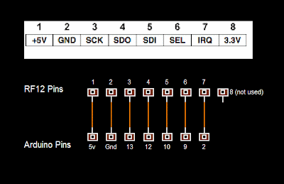
3.      Note the PCB has the connecting Arduino pins marked on it.


4. Connect the RF12 boards to the Arduinos according to the above diagram. At this point I have two RF12 Arduino transceivers all wired up.

Setting Up and Testing the Transceivers

I don’t pretend to understand how all this code and library works, but it works ok and that’s good enough for me, at least for now.

1.      Download and install the RF12 Arduino library  http://jeelabs.org/pub/snapshots/RF12.zip

2.      Open the RF12 demo sketch.
Note I had to change the Baud rate of the serial connection to get it to work  ie
void setup() {
    Serial.begin(57600); CHANGE to Serial.begin(9600);
........ others may work too..........

Load the sketches to the Arduinos and refer to this page:
http://jeelabs.org/2011/02/02/meet-the-rfm12b-board/. I got something that looks like this when I opened the serial monitor(s):


...plus some other stuff I didn’t need to worry about.

I set my RF12’s to 868 MHz working in group 10 and each node ID labelled in sequence 1, 2 etc... The RF12 demo stores these data in memory so the nodes remember what the freq is and their ID’s.

It’s tricky keeping track of which nodes are on which serial COM and which Arduino. I am uploading to or sending / receiving serial data from at least two. Obviously the more Arduinos connected the worse it gets, so I label the Arduino with tape and write the COM number on it.

9. I typed this into the serial monitor for node 1:

8b
10g
1i

and this for node 2:

8b
10g
2i

10. For each node, I tried sending max-size packet with ack [acknowledge]


and in return I got in return something like this for node 1, group 10:

Current configuration:
 A i1 g10 @ 868 MHz
> 0t
test 0
 -> 66 b
OK 193

and in return I got in return something like this for node 2, group 10:

B i2 g10 @ 868 MHz
> 0t
test 0
 -> 66 b
OK 193

That tells me the nodes are successfully transmitting and receiving data-packets – huzzah!

It’s not absolutely necessary, but I could go ahead and test further by playing with the packetbuf demo (remember to change baud rate if you get a problem). I am using packetbuf code in my RC device.

TIPS:
To avoid some of the pitfalls and frustrations I got into, I recommend steps 2. through to 9. are followed if you use your Arduino or AVR chips for other things, because the memory may get overwritten. This happened to me on a few occasions. Also label which Arduino is using which COM connection. It will save lot’s of grief as the number of nodes increase, especially if you are loading different sketches to different Arduinos.

Beware of using delay() with RF12 modules. They use interrupts to operate, hence Arduino pin 2 is used, which is one of the external interrupt pins. Arduino delay() plays havoc with interrupts so it can't be used. Use blink-without-delay, which is given as an example with the Arduino IDE. Alternatively, I  use delayMicroseconds() which does not interfere with the packet buffer code I am using. I think purists may prefer blink-without-delay, however.